FQ101 will not be held responsible for any damage incurred as a result of working on your car's wiring systems. This information is for reference only.
The following information has been collected from a 2005 Brabus Roadster and a 2004 Roadster 80. Please note that this guide is only applicable for Roadsters (452). There are some fundamental differences with the fortwo SAM wiring configurations and therefore you should not use this guide if you have a fortwo.
To access the wiring of your SAM follow this guide. The connectors on the back of the SAM are as follows:
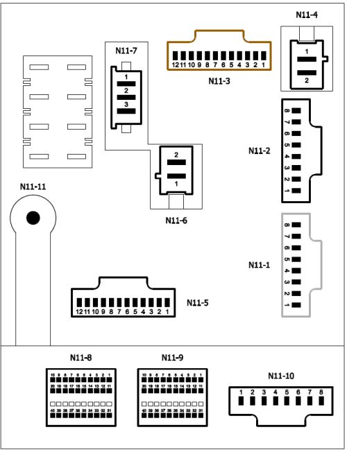
Note that connectors 21-30 are not used for N11-8 or N11-9. Details on how to access these are shown at the bottom of this guide.
If you would like a summarised wiring diagram, you can download and print off the following pdf. It may be easier to use this when working in your footwell:
![]()
| N11-1 | Wire Size | Wire Colour | Fuse No. | Fuse Rating | Function | To/From SAM |
|---|---|---|---|---|---|---|
| 1 | 1.5 1.5 |
Black/Yellow Black/White |
4 | 30 | Left electric window Right electric window |
From |
| 2 | 2.5 | Black/Red | 3 | 20 | Interior heater fan. Heated seats control modules | From |
| 3 | 1.5 | Black/Yellow | 8 | 20 | Ignition coils: cylinders 1,2,3 | From |
| 4 | 1.5 1.5 |
Pink/Red Pink/Red |
2 | 20 | Wiper stalk supply Wiper motor (via relay) |
From From |
| 5 | 1.0 | Violet | 13 | 15 | Front fog lamp supply (constant live) | From |
| 6 | 2.5 | Red/Black | 14 | 25 | ESP control unit supply (constant live) | From |
| 7 | 2.5 | Pink | 12 | 15 | Radio supply (constant live) | From |
| 8 | - | - | 1 | 15 | Starter motor relay | From |
| N11-2 | Wire Size | Wire Colour | Fuse No. | Fuse Rating | Function | To/From SAM |
| 1 |
0.5 |
Brown/Green |
- | - | MEG (ECU) | From |
| 2 | 2.5 | Black | 28 | 30 | Heated rear window, heated wing mirrors | From |
| 3 | 1.5 | Red/White | 11 | 7.5 | Instrument cluster, pods, trip computer, key receiver (constant live) | From |
| 4 | 0.35 |
Red/Green |
11 |
7.5 |
Triangle (hazard lights, central locking buttons - constant live) |
From |
| 5 | 4.0 | Brown | - | - | Ground for electric soft top relay | From |
| 6 | 4.0 | Yellow | 29 | 25 | Soft top motor (via relay) | From |
| 7 | 0.35 | Blue | - | - | MEG (ECU) Gear select system (constant live) | From |
| 8 | 4.0 | Red/White | 29 | 25 | Soft top motor (via relay) | From |
| N11-3 | Wire Size | Wire Colour | Fuse No. | Fuse Rating | Function | To/From SAM |
| 1 |
- |
- | 17 | 15 | Rear wiper - not used on any Roadster | - |
| 2 | 1.5 | Grey | 18 | 7.5 | Crash system (airbags, seat belts, ECU, ESP) | From |
| 3 |
0.5 |
Red/Yellow |
19 | 7.5 |
Electric wing mirror switch & supply |
From |
| 4 | 1.0 |
Blue |
20 |
15 |
Front fog light relay, trip computer, radio, heated seat modules, power steering, rain/light sensor switched live supply. |
From |
| 5 | 1.5 | Blue/Yellow | 21 | 15 | Cigarette lighter | From |
| 6 | 1.0 | Grey/Red | 22 | 7.5 | Right headlight (low beam) | From |
| 7 | 1.0 | Blue/Green | 23 | 7.5 | Left headlight (low beam) | From |
| 8 | 1.0 | White | 24 | 7.5 | Right headlight (full beam) | From |
| 9 |
0.5 |
White/Blue |
25 | 7.5 |
Dashboard indicator (full beam) |
From |
| 10 | 1.5 | Red/Black | 16 | 10 | Fuel pump, fuel level sensor | From |
| 11 | 1.0 | Blue/Red | 26 | 15 | Brake lights (via brake switch - constant live) | From |
| 12 | 1.5 | Red/White | 27 | 7.5 | MEG (ECU) power supply (constant live) | From |
| N11-4 | Wire Size | Wire Colour | Fuse No. | Fuse Rating | Function | To/From SAM |
| 1 |
4.0 |
Red/Black | - | - | Ignition switch in position 1 (switched live supply) | To |
| 2 | 4.0 | Red/Blue | 30 | 40 | Gearshift system | From |
| N11-5 | Wire Size | Wire Colour | Fuse No. | Fuse Rating | Function | To/From SAM |
| 1 |
- |
- | - | - | Not used | - |
| 2 | - | - | 17 | 15 | Rear wiper - not used on any Roadster | - |
| 3 |
1.5 |
Red |
2 | 20 | Wiper motor (via external relay) | From |
| 4 | - |
- |
- |
- |
Wiper motor relay signal | - |
| 5 | 1.5 | Brown | - | - | SAM wiper motor relay ground | From |
| 6 | 0.75 | Red/White | 5 | 7.5 | Indicator, headlight stalk (constant live) | From |
| 7 | 1.0 | Brown/White | 6 | 7.5 | Right side lights, interior backlights, numberplate lights | From |
| 8 | 0.5 | Red/Green | 12 | 15 | Interior light, rain/light sensor supply (constant live) | From |
| 9 |
0.5 |
Brown/Yellow |
7 | 7.5 |
Left front side light |
From |
| 10 | 1.5 | Green | 9 | 10 | Engine connector (ESP) | From |
| 11 | 0.5 | Black/Pink | 10 | 15 | MEG (ECU) Fuel pump instruction | From |
| 12 | 2.0 | Yellow/Black | 10 | 15 | MEG (ECU) Engine run signal | From |
| N11-6 | Wire Size | Wire Colour | Fuse No. | Fuse Rating | Function | To/From SAM |
| 1 |
2.5 |
Blue | 1 | 25 | Starter motor | From |
| 2 | 2.5 | Pink | 32 | 30 | Exhaust CAT preheater | From |
| N11-7 | Wire Size | Wire Colour | Fuse No. | Fuse Rating | Function | To/From SAM |
| 1 |
3.0 |
Red/White | 35 | 30 | EPS - Power steering (constant live) | From |
| 2 | 4.0 | Red | 34 | 50 | ESP - Traction Control (constant live) | From |
| 3 | 4.0 | Red/Black | 33 | 50 | Ignition starter switch (constant live) | From |
| N11-8 | Wire Size | Wire Colour | Function | To/From SAM | ||
| 1 |
- |
- | - | - | ||
| 2 | 0.5 | Brown/White | Ground for boot release | From | ||
| 3 |
0.5 |
Grey/Red | Windscreen wiper stalk in intermittent position | To | ||
| 4 | 0.5 | Yellow/White | Right door microswitch (door open) [swap with 19 for LHD/RHD conversion] | From | ||
| 5 | - | - | - | - | ||
| 6 | - | - | - | - | ||
| 7 | - | - | - | - | ||
| 8 | 0.5 0.5 |
Yellow/Green Yellow/Green |
Crash signal two airbags Crash signal side airbags |
From |
||
| 9 |
0.75 |
Pink/Red | Wiper motor park signal from wiper motor | To | ||
| 10 | 0.5 | Green/Blue | Console backlight signal from headlight stalk | To | ||
| 11 | 0.35 | Black/Green | Cruise control supply | From | ||
| 12 | - | - | - | - | ||
| 13 | 0.5 | Brown | Ground for wiper system | From | ||
| 14 | 0.35 | White/Black | CAN interface High (to instrument cluster) | Both | ||
| 15 | 0.35 | Brown/Red | CAN interface Low (to interface cluster) | Both | ||
| 16 | 0.5 | Red | Steering wheel horn and paddle wheel | From | ||
| 17 | 0.5 | Yellow | Wiper stalk in fast position (up two positions) | To | ||
| 18 | 0.5 | Blue/Black | Central locking system door microswitches | From | ||
| 19 | 0.5 | Yellow/Red | Left door microswitch (door open) [swap with 4 for LHD/RHD conversion] | From | ||
| 20 | 0.5 | Green | Remote boot release switch | From | ||
| 31 | 0.5 | Blue | Interior fan in OFF position (to disable aircon) | To | ||
| 32 | 0.5 | Blue/White | Roof bar microswitches (to stop electric roof) | From | ||
| 33 | 0.5 | Pink/Black | Boot microswitch (to stop electric roof) | From | ||
| 34 | 0.5 | Grey | Hand brake indicator switch | From | ||
| 35 | 0.5 | White | Electric soft top switch | From | ||
| 36 | - | - | - | - | ||
| 37 | - | - | - | - | ||
| 38 | 0.5 | Grey/Blue | Ignition switch in position 2 | To | ||
| 39 | 0.35 | White/Black | CAN interface Low (to MEG and steering assist) | Both | ||
| 40 | 0.35 | Brown/Red | CAN interface High (to MEG and steering assist) | Both | ||
| N11-9 | Wire Size | Wire Colour | Function | To/From SAM | ||
| 1 | 0.75 | Black/White | Left indicators | From | ||
| 2 | 0.35 | Grey | Aircon first stage from triangle | To | ||
| 3 | 0.35 | White/Grey | OBD port pin 1 | From | ||
| 4 | 0.5 | Grey/Blue | Interior light (signal from door open) | From | ||
| 5 | - | - | - | - | ||
| 6 | 0.5 | Pink | Front fog lamp relay ground (from external fog lamp relay) | To | ||
| 7 | 0.35 | Pink/Red | Cruise control (from stalk) | To | ||
| 8 | - | - | - | - | ||
| 9 | 0.5 | Blue/Yellow | Auto lights switch | From | ||
| 10 | 0.35 | Green/Brown | Cruise control (from stalk) | To | ||
| 11 | 0.75 | Black/Green | Right indicators | From | ||
| 12 | 0.35 | Violet/Blue | Hazard light switch (from triangle) | To | ||
| 13 | 0.35 | Blue | Central locking switch (from triangle) | To | ||
| 14 | 0.5 | Violet | LIN bus to trip computer / pods / rain & light sensor | Both | ||
| 15 | - | - | - | - | ||
| 16 | 0.5 | Blue/White | Wiper system relay ground | To | ||
| 17 | 0.35 | Yellow/Black | Front fog lamp switch (on/off signal) | From | ||
| 18 | 0.5 | Blue/Yellow | Auto lights switch | From | ||
| 19 | - | - | - | - | ||
| 20 | 0.5 | White | Infra red / Radio key receiver data link | Both | ||
| 31 | 0.35 | Green | Aircon second stage from triangle | To | ||
| 32 | 0.35 | Black/Red | Rear window (and electric wing mirror) heater switch from triangle | To | ||
| 33 | 0.5 | Red/Yellow | Rear fog light switch signal from headlight stalk | To | ||
| 34 | 0.5 | Yellow | High beam flash signal from headlight stalk (stalk pulled back) | To | ||
| 35 | 0.5 | Yellow/Green | Low beam signal from headlight stalk (stalk twisted to 2nd position) | To | ||
| 36 | 0.5 | Green/Blue | Wiper stalk in slow constant wipe position (up one position) | To | ||
| 37 | 0.5 | Yellow/Black | Fog light switch | From | ||
| 38 | 0.5 | Blue | Right indicators from headlight stalk | To | ||
| 39 | 0.5 | Black/Green | Left indicators from headlight stalk | To | ||
| 40 | 0.5 | Red/Green | Washer pump signal from wiper stalk (stalk pulled back) | To | ||
| N11-10 | Wire Size | Wire Colour | Fuse No. | Fuse Rating | Function | To/From SAM |
| 1 |
1.0 |
Brown |
- | - | Ground | From |
| 2 | 1.5 | White | - | - | Aircon compressor | From |
| 3 | 2.5 | Brown/Green | - | - | Front radiator fan | From |
| 4 |
1.0 |
Grey/Blue |
31 |
30 |
Central locking (doors & fuel cover) Lock/Unlock | Both |
| 5 | 1.0 | White/Blue | 31 | 30 | Central locking (doors & fuel cover) Lock/Unlock | Both |
| 6 | 1.5 | Blue/Red | 31 | 30 | Horn | From |
| 7 | 1.5 | Yellow | 15 | 15 | Intercooler / Chargecooler fan | From |
| 8 | 0.5 | Red | 31 | 30 | Boot release solenoid | From |
| N11-11 | Wire Size | Wire Colour | Fuse No. | Fuse Rating | Function | To/From SAM |
| 1 | 16.0 | Red | - | - | Main supply from battery | To |
| R | Wire Size | Wire Colour | Fuse No. | Fuse Rating | Function | To/From SAM |
| R1 | - | - | - | - | - | - |
| R2 | - | - | - | - | - | - |
| R3 | - | - | - | - | - | - |
| R4 | - | - | - | - | - | - |
| R5 | - | - | - | - | - | - |
| R6 | - | - | - | - | - | - |
| R7 | - | - | - | - | - | - |
| R8 | - | - | - | - | - | - |
| R9 | 1.5 1.5 |
Red Red |
44 |
25 | Heated seats | From |
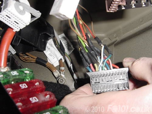
When tracing the wiring, we found the following spliced wiring for N11-10. In this case, the wiring colours from the above table apply after the splices and not immediately after the SAM connector:
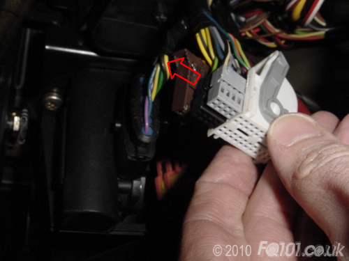
To access the wiring connectors for N11-8 and N11-9, you need to remove the outer casing. Pins 1-20 are attached to a grey connector with Pins 31-40 in a black connector. Each of these are held in the outer case with two white clips indicated below. Use a small screwdriver to push these back whilst pulling the wiring gently.
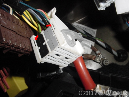
The connectors should now slide out of the case.
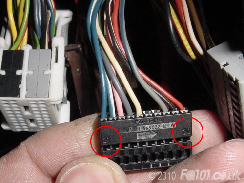
In case you forget which way round the connectors fit into the outer case, each one is labelled with its pin value and a direction arrow. The connectors are slid into the case in the direction of the arrow where they will click back into place.