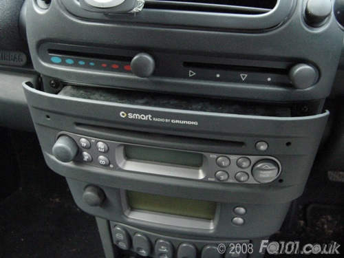
Remove the radio by using the removal clips. If you cannot find your clips anymore, use alternative removal clips.
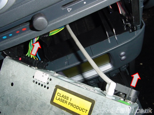
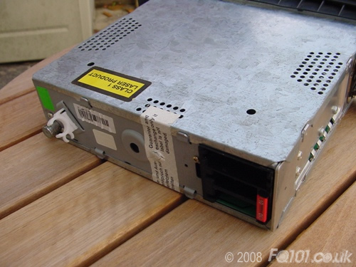
Slide the radio out and disconnect the aerial, power and speaker connectors. Remove the radio from the car.
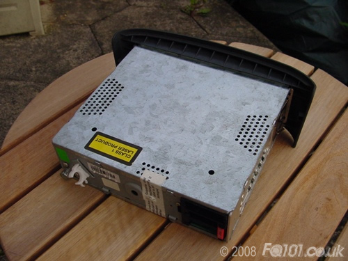
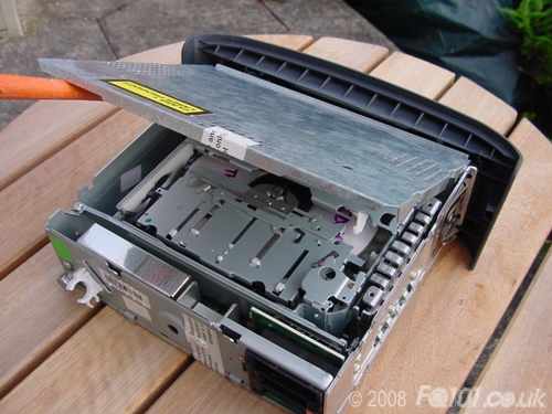
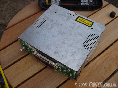
The top and bottom sections of the radio need to be levered apart at the back. This will break the warranty seal.
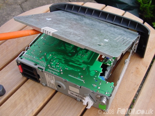
Remove each of the sections as shown.
Pull off the volume control knob.
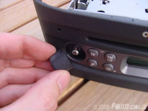
The fascia will now unclip from the front.

You may choose to put the top and bottom sections back on the radio whilst you work on the LEDs.
The following layout is for the standard Grundig CD Head Unit.
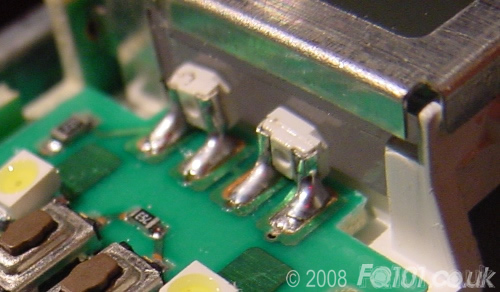
Click on the picture to make larger. LED orientation is shown with a triangle pointing to the cut-out on the negative side of the LED. The screen is lit with side LEDs. SMT PLCC-2 LEDs can be used to replace these when mounted at 90 degrees - see picture at bottom of page for details. Observe correct polarity when soldering.
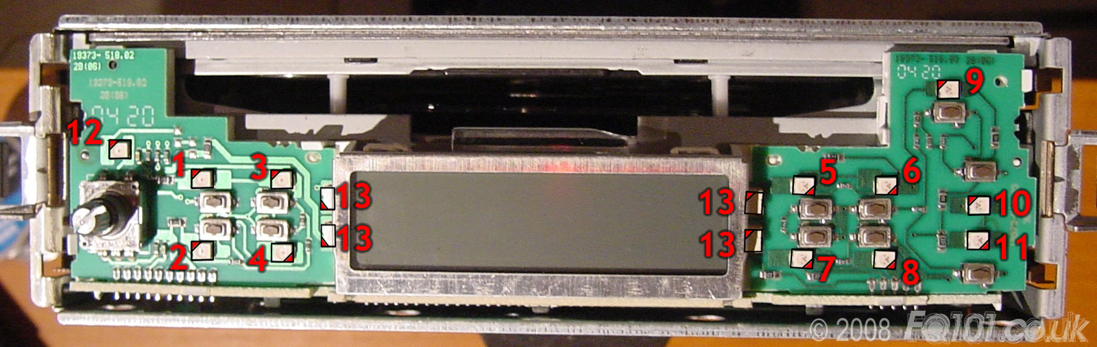
| No. | Type | OEM Colour | Function |
|---|---|---|---|
| 1 | PLCC-2 | Warm White | TP Button |
| 2 | PLCC-2 | Warm White | Audio Settings |
| 3 | PLCC-2 | Warm White | FM/AM Button |
| 4 | PLCC-2 | Warm White | CD Button |
| 5 | PLCC-2 | Warm White | Button '1' |
| 6 | PLCC-2 | Warm White | Button '2' |
| 7 | PLCC-2 | Warm White | Button '3' |
| 8 | PLCC-2 | Warm White | Button '4' |
| 9 | PLCC-2 | Warm White | CD Eject Button |
| 10 | PLCC-2 | Warm White | Tune Up Button |
| 11 | PLCC-2 | Warm White | Tune Down Button |
| 12 | PLCC-2 | Warm White | Volume Backlight |
| 13 | Side LED | Warm White | LCD Backlight |
Detail of soldering PLCC-2 LEDs to replace side LEDs: