

All smarts will, at some time, require an engine rebuild. This is typically (but by no means guaranteed!) over 50,000 miles.
This guide principally focuses on replacing the piston rings, big-end shells, conrod bolts and timing chain guide. Inspection was made of the valves, but it was not deemed necessary to replace them here. This guide does show cylinder head removal so you are half way to removing the valves anyway.
The parts used here are:
- Piston Rings (x3) SQ0019611V001
- Con Rod Bearings (x1 set) SQ0019614V001
- Cylinder head bolts A0029903722
- Head gasket (x1) SQ0003086V003
- Crankcase breather pipe (not essential) 0003134V008
- Sliding Rail (timing chain guide) A1600520116
- Screws with rounded heads (Conrod bolts) Q0022099V000
- Thermostat (not essential) A1602000315
- Shield Manifold (turbo gasket) SQ0003159V005
- Stud bolt M6 (manifold studs) (x7) SQ0002489V000
- Bundmutter M6 (manifold nuts) (x7) SA1121420072
- Stud (exhaust studs) (x2) SA0019903914
- Tapered flange nuts (for exhaust studs) (x2) SQ0005085V0000
Before starting, remove the engine oil. This guide may be of use for this.
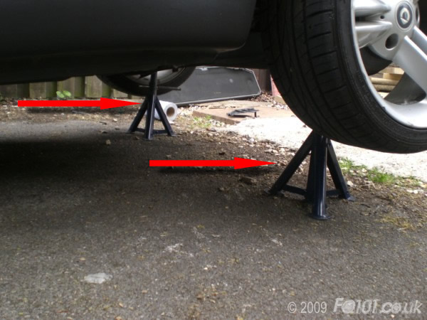
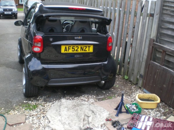
Remove the rear panels for more 'light' under the car, raise up the car on tall axle stands and chock the front wheels.
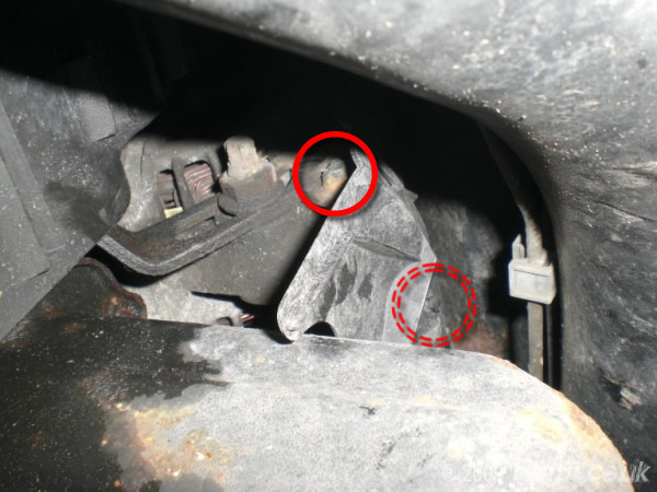
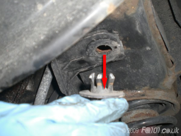
Locate and remove the alternator shield (if present); it is held in with 2 plastic catches on either side of the cover.
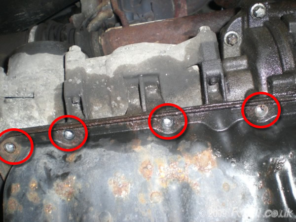
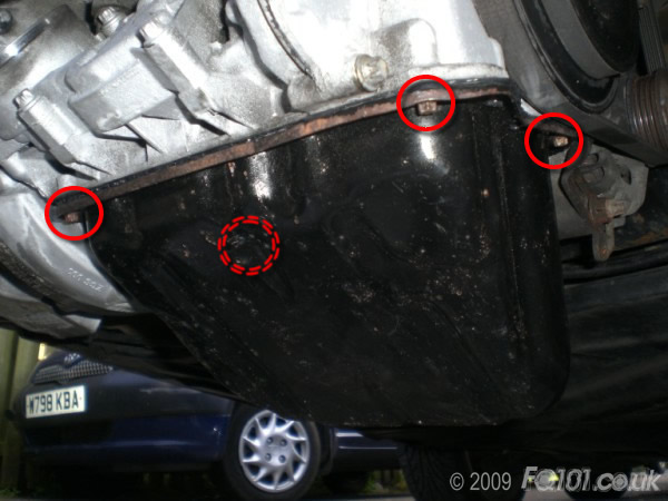
Remove all 14 sump bolts using an E8 torx socket.
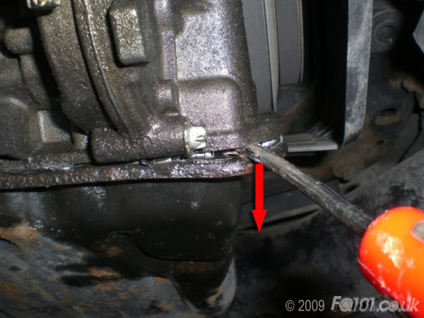
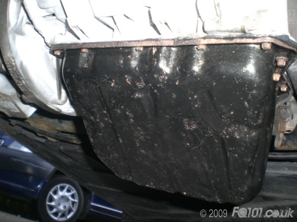
The sump will be securely sealed against the lower block with engine sealant. Separate carefully using a thin wedge/screwdriver. Be careful not to score the surface on the lower block face.
Once you have room to pull the sump down with your fingers, do so - NOTE: there will still be a quantity of oil still in the sump so be very careful and prepare to clean up or catch the excess oil.
To allow more access as the work goes on, we found it easier to remove the central engine mount allowing the engine to pivot down giving better access on all bolts. Support the engine on a jack and lower down slowly when doing this.
To gain proper access to the conrod bolts and the big-end bearing shells, you need to split the block by removing the lower half.
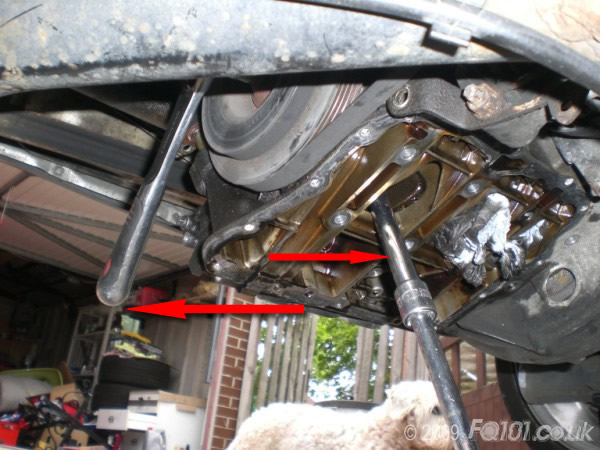
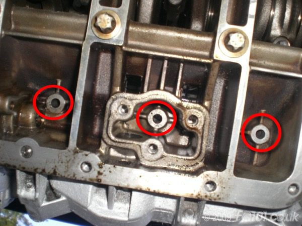
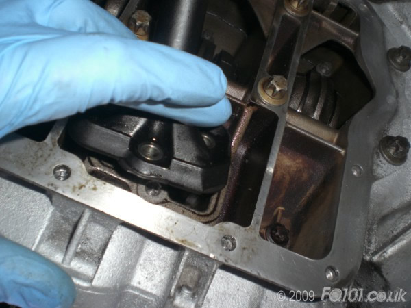
Start by removing the oil pick-up pipe (3x E10 bolts)
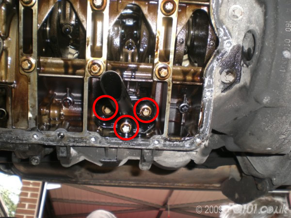
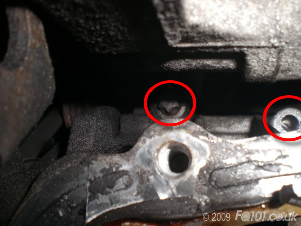
Remove the 3x E10 bolts mounted inside the lower half of the block.
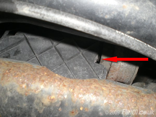
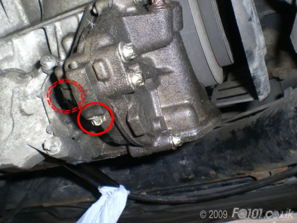
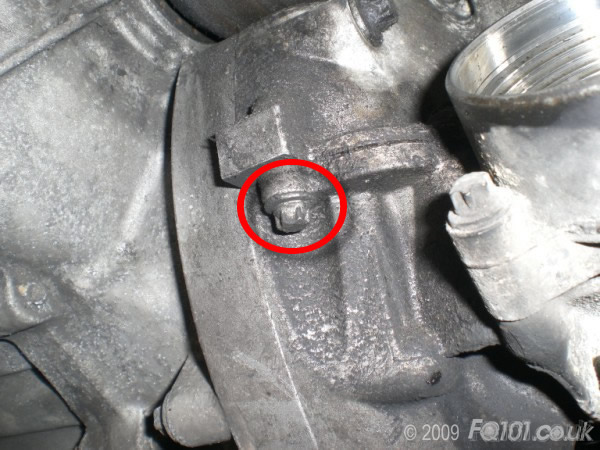
Remove the 4x E10 bolts from the gearbox side, one of which is tucked 'inside' the intercooler ducting. This one can be accessed from the n/s wheelarch.
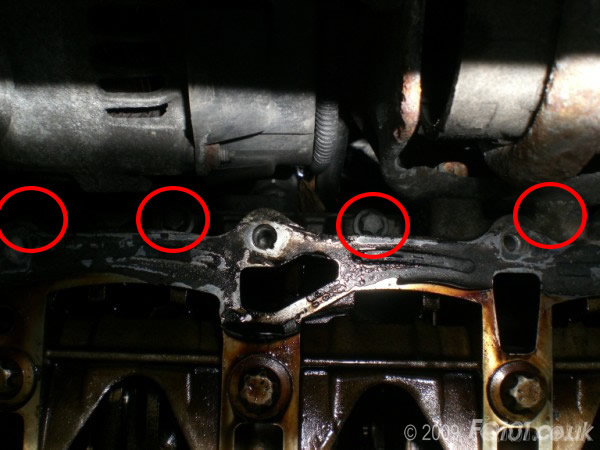
Remove the remaining E10 bolts from the lower block.
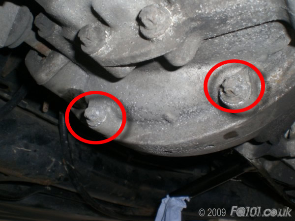
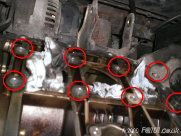
Remove the 8 E12 Crankshaft securing bolts.
Remove the plastic push clips for the crankshaft pulley cover, and remove the cover.
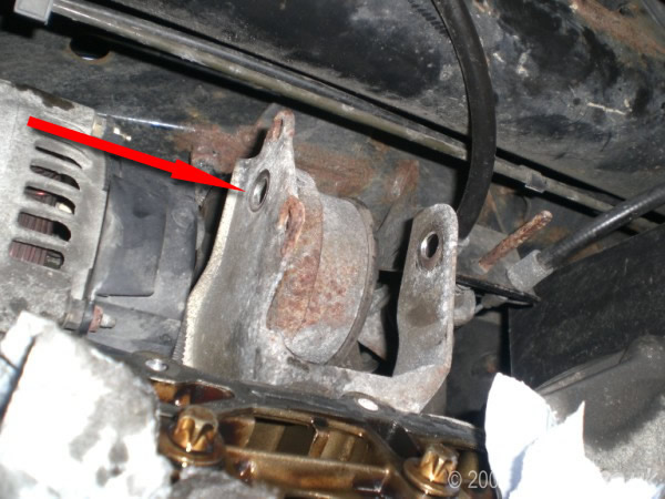
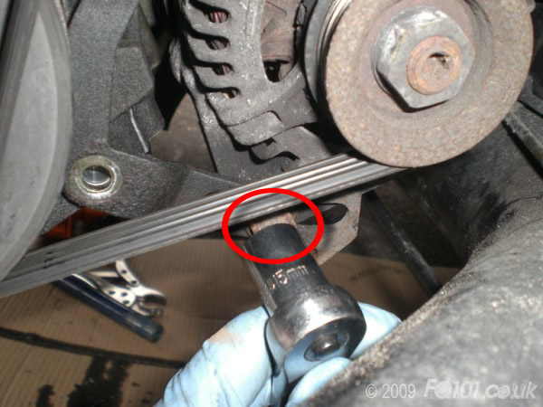
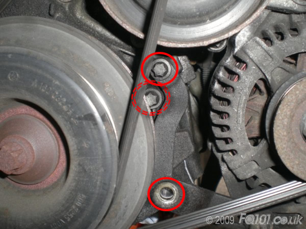
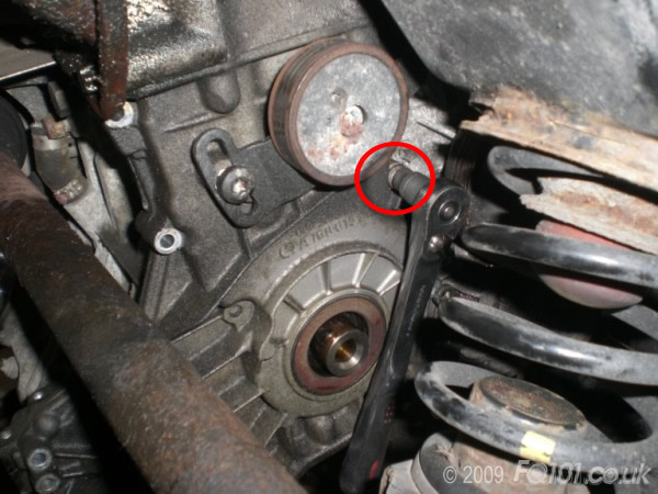
Remove the alternator tensioner mount - slacken the tensioning bolt first (15mm socket).
Remove the 2x E10 alternator mount bolts; you can see 3, but cannot remove the final one with the crank pulley in situ.
Use a T45 torx bit to slacken the air-con (if fitted) tensioner. Then remove the belts.
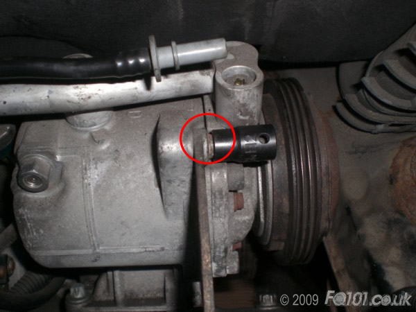
Use a bar to wedge the crankshaft from moving. We found it easiest to hold the bar against the crank webbing.
Then use an E18 socket on a long breaker bar to remove the crankshaft bolt.
Remove the crankshaft pulley and retain the spacer. To give more room to move, we removed the dipstick, which is held in place with a single E10 bolt.
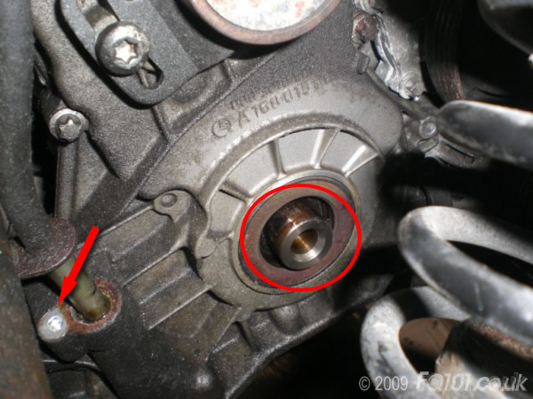
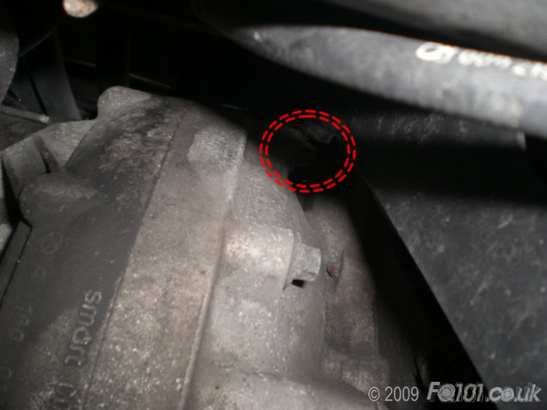
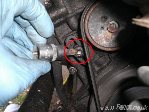
You can now remove that third alternator mount bolt.
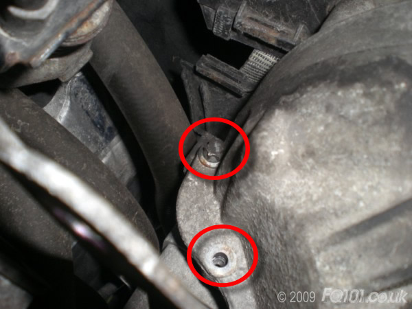
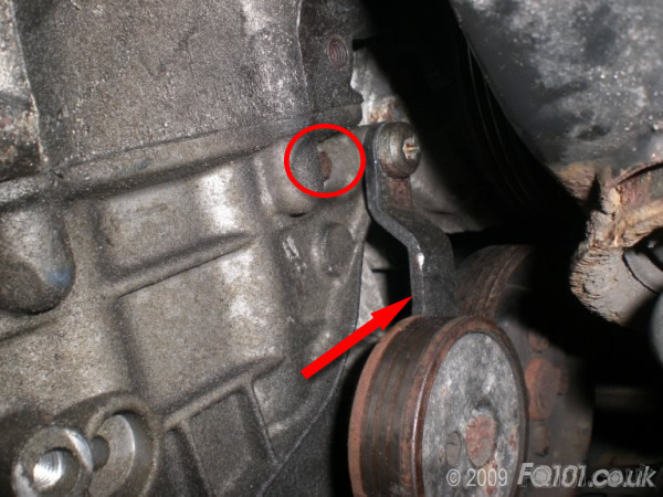
Slacken the air-con tensioner top mount enough to allow it to pivot out of the way. This will reveal another E10 bolt next to it which you can then remove.
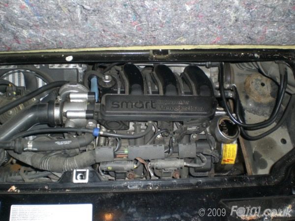
The final 2 remaining bolts are unfortunately accessed from inside the cylinder head. Use this guide to remove the inlet manifold & injectors.
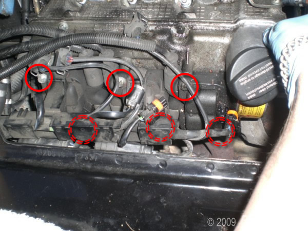
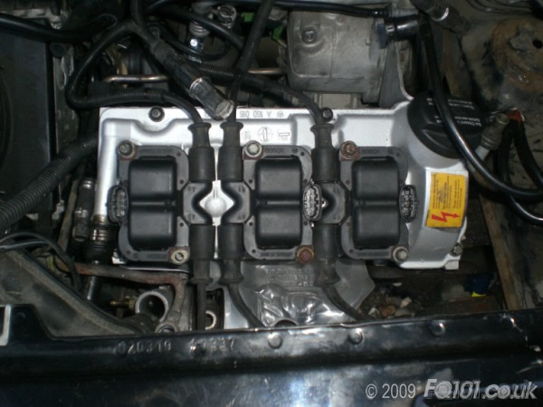
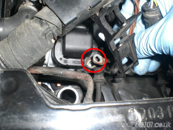
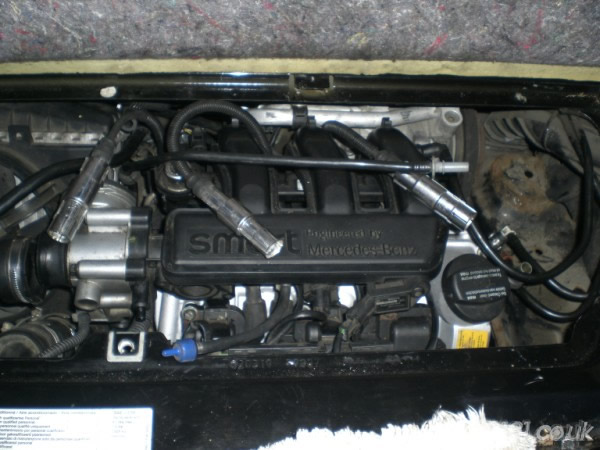
Now remove the coil packs from the top of the rocker cover. They are held on with 2 E10 bolts each (x3).
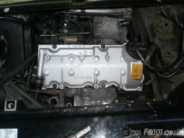
Remove the rocker cover (6 E10 bolts) and lift off to show the final 2 securing E12 bolts.
Gently pry/tap apart the timing case from the side of the engine. It will be stuck with sealant, so be careful not to damage the mating faces.
What you will find at this stage is that the cylinder head gasket seals the top edge of the timing case - it is likely that this will tear or deform. Don't worry, as you need to remove the head anyway.
Pull the timing case clear of the engine.
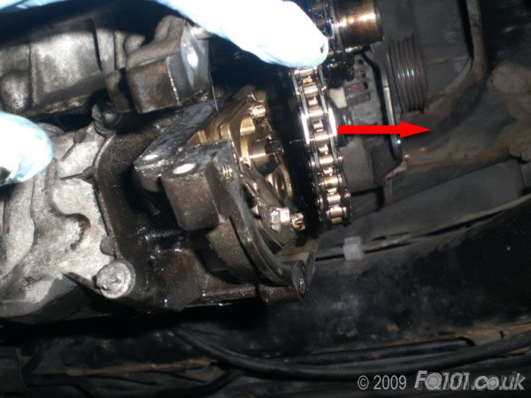
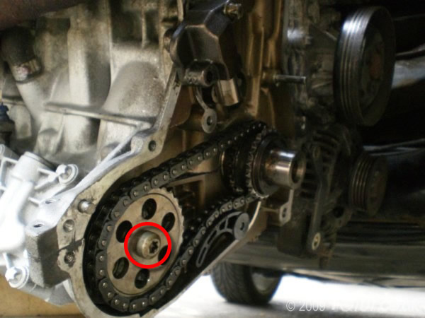
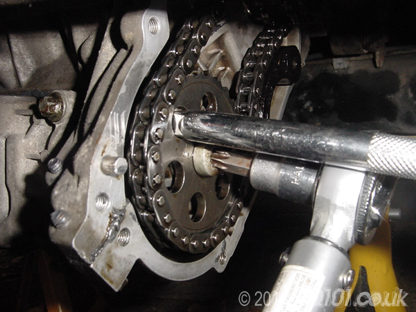
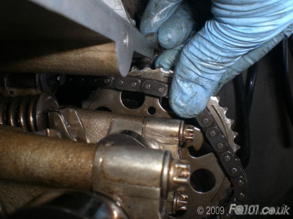
Remove the oil pump sprocket using a T45 Torx bit. To hold it while you slacken the bolt, push a small bar through one of the holes in the sproket. This will trap against the casting of the block allowing you to free the bolt.
Pull the sprocket out of the way - you do not need to remember the position of the sprocket, so you can remove it out of the way completely.
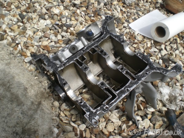
Now, the only thing holding the lower half of the block on is the sealant.
Gently pry the lower half away until is separates.
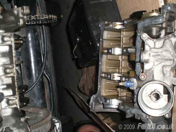
The con-rod caps are now fully accessible.
To remove the other con-rods, you may find it easier to rotate the crank to get the appropriate piston at BDC.
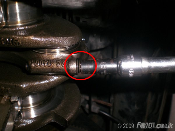
Use an E8 socket to remove the bearing caps.
IMPORTANT - remember which cap belongs to which rod - they are matched.
The bearing may come away in the cap, but if not, just remove from the crank.
You can now release the piston off the crank by just pushing it back up into the cylinder.
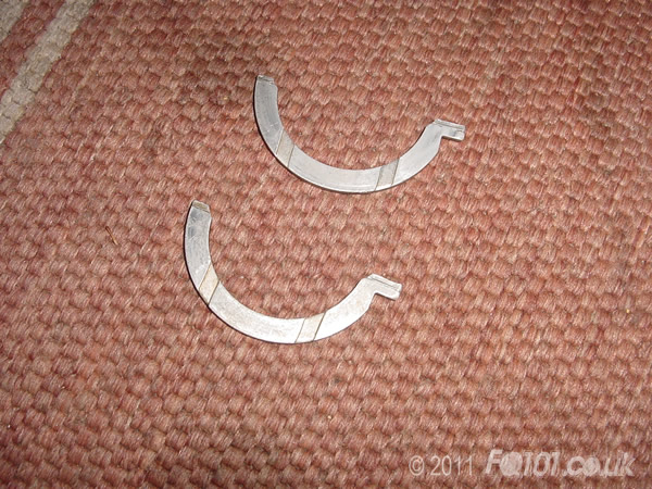
While moving the crank, you may find that the crank bearing may drop out. They look as follows:
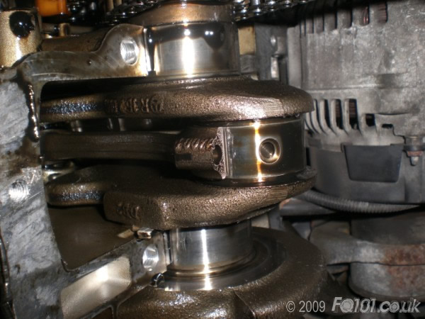
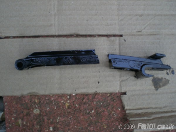
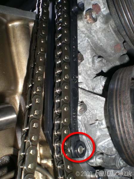
Rather concerningly we found that the timing chain guide rail had snapped in two; whilst this is not uncommon, it would have been very unwise to continue running the engine in this state.
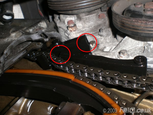
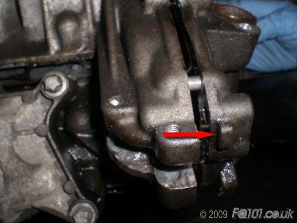
The lower pivot of the rail slides onto a pin; the upper mount clips onto a bar in the head.
Simply pull off the head and remove from the pin.
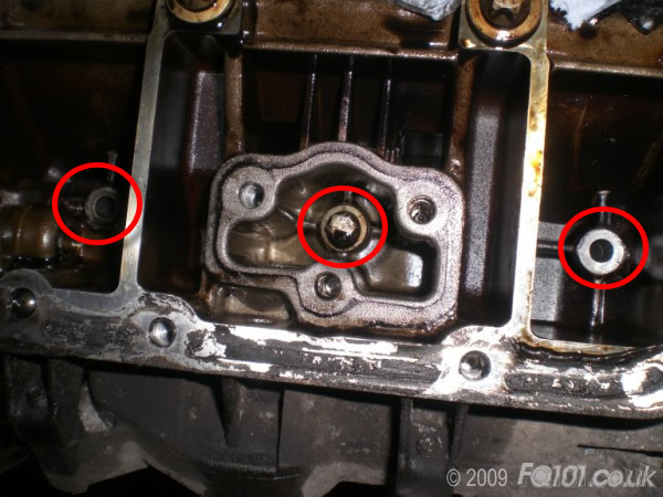
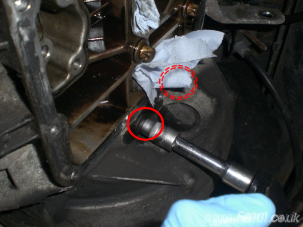
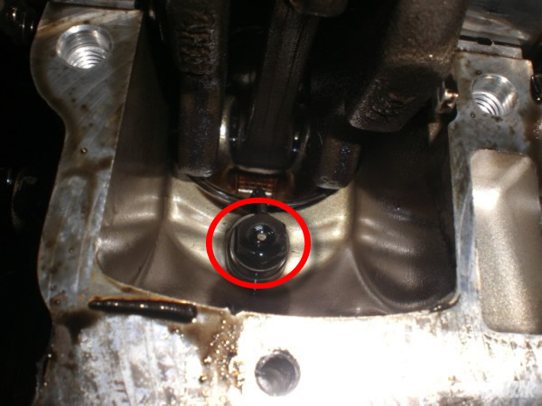
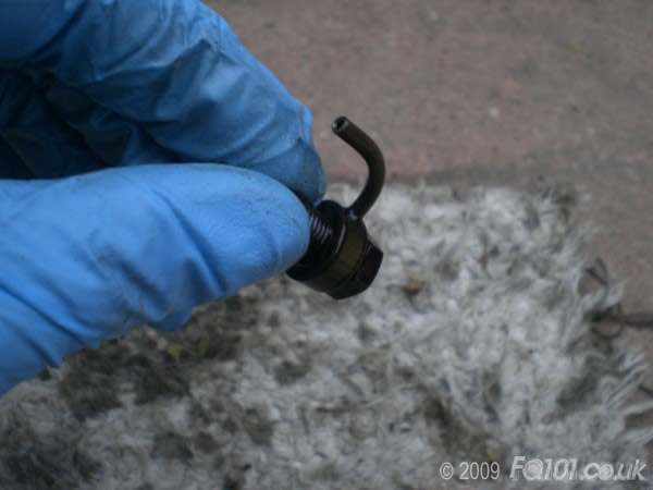
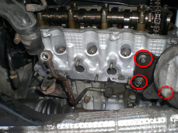
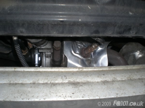
Whilst under the car, we thought it was worth removing the piston top sprayers to check for condition. They are easy to remove using a 13mm socket (and refit).
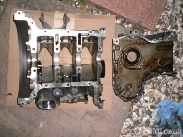
Due to the casting of the main block, unfortunately you can't actually pull the pistons down through through the bottom.
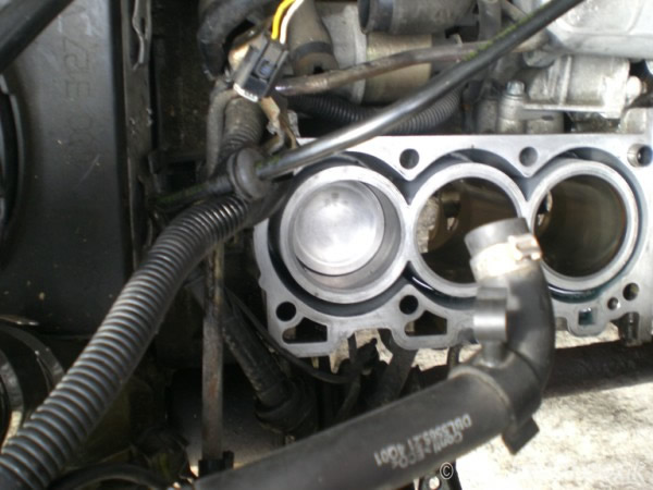
Therefore the cylinder head now needs to be removed.
Use an E12 to remove the top mount bolt for the air-con compressor (if fitted).
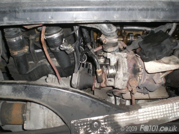
Remove the TIK from the turbo, plus any pipe-work which is still attached, the oil feed, the coolant lines, vacuum lines etc.
The plan is to remove the cylinder head with the turbo still attached.
You will now need to support the underside of the block on a jack (or similar) with a block of wood to avoid damage, as one of the engine mounts is attached to the cylinder head.
Remove the engine mount (3xE12 bolts).

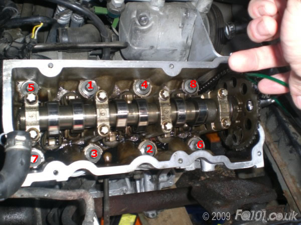
To release the head, use an E18 socket to firstly slacken, then remove in the order shown.
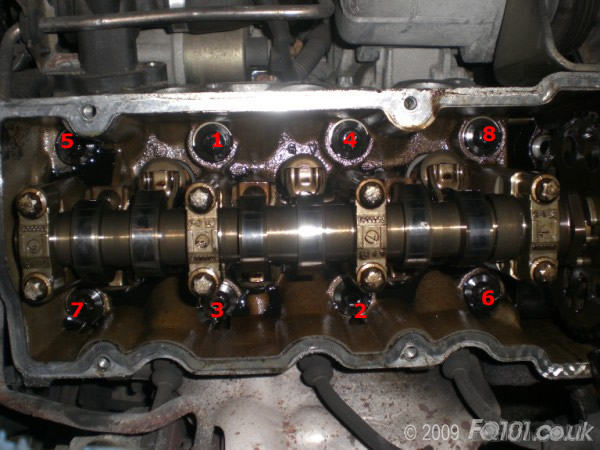
The head should now be free to be removed from the block.

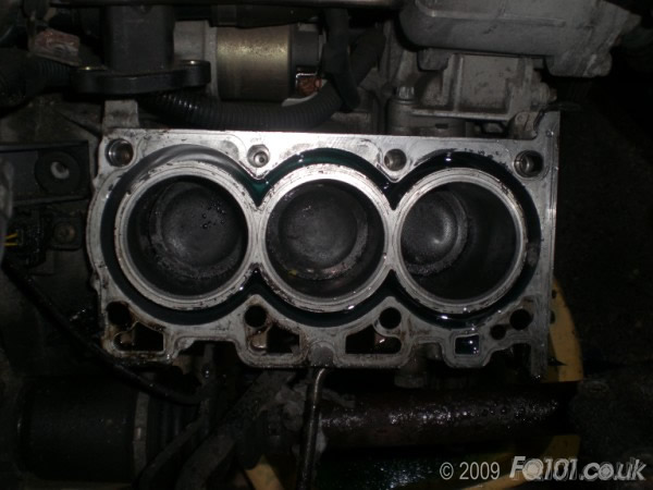
You can now push the pistons out of the cylinders from below.
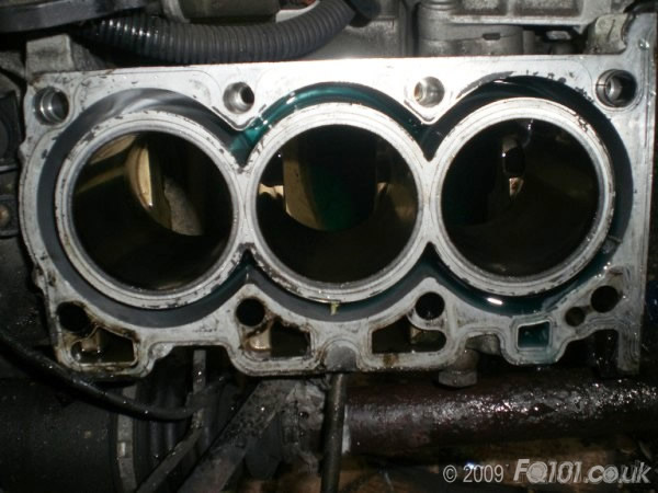
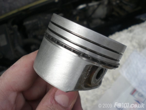
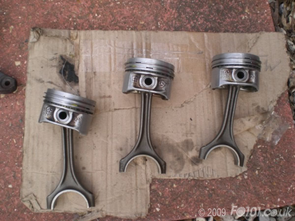
Inspect the valves and pistons for signs of damage - we noted an awful lot of carbon deposits in the engine, but luckily no damage.
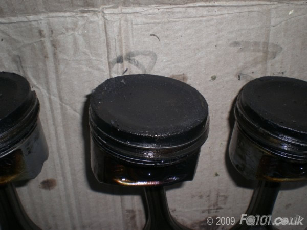

The main notable discovery was sticky piston rings on all cylinders, but more prominent on cylinder 1.
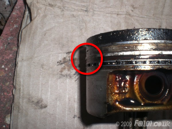
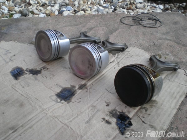
We cleaned up the pistons with a combination of strong chemical de-greasers and fine-grade wet & dry paper to remove the more stubborn deposits.
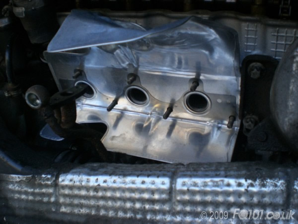
The turbo was removed from the cylinder head, only to discover that the gasket had been blowing from 2 of the 3 exhaust ports, which really would have affected the overall running of the car.
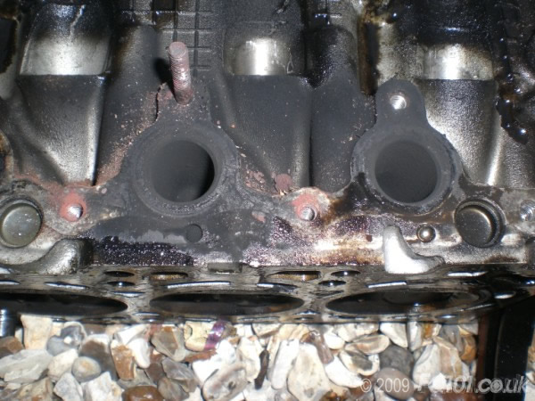
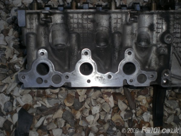
We cleaned the mounting face for the turbo.
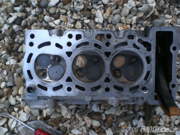
Moving onto checking the valves for damage, we used the same cleaning method as the pistons.
You can see the left valves/face have been done.
Luckily there was no damage to the valves and no sign of any issues.
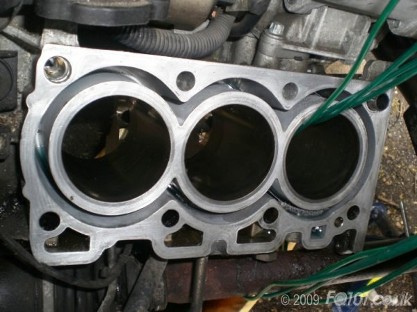
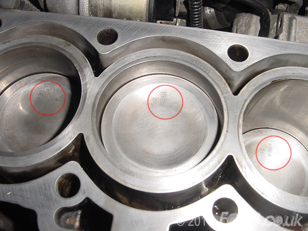
We decided the cylinders did not require honing; the cross-hatching was still visible and the surface did not have a glass like appearance.
If you cannot see any markings whatsoever on the bores, and it does have a 'glass-like' finish, then it's worth running a honing tool down the bore.
When I refer to marks, we are talking smaller than hair-line cross hatching... not scoring or physical damage - which is clearly a big problem!.
The block face was cleaned up.
Fitting the new piston rings to the pistons requires no specialist tools, but you must install them in the correct order.
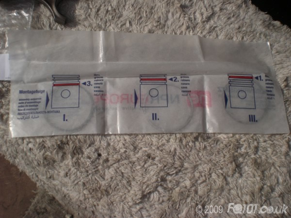
In the FIRST step, the third ring is actually made up of 3 separate rings: 2 thin outer and 1 thick oil scraper ring.
Put the thick ring onto the piston first, and locate it in the recess accordingly. Only then can you fit the 2 thinner rings. Don't twist them too much on the piston, as they will snap.
As a tip, feed it into the first recess first, then down into the second recess, and then finally down into the third, instead of trying to stretch it into the third immediately.
The SECOND ring is actually the same as the third, but for consistency follow the correct location.
And again repeat for the THIRD ring.
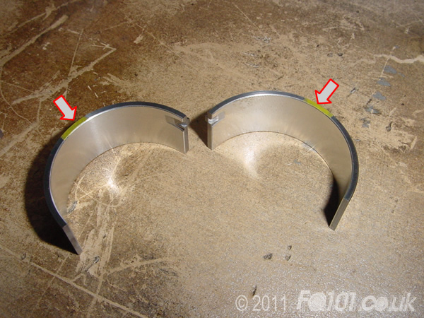
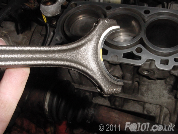
Take your new conrod bearings (big end shells) and pair them up. Note that they have yellow marks on either side to help with the pairing.
Locate the bearing in the conrod as shown. You will see that they can only fit one way.
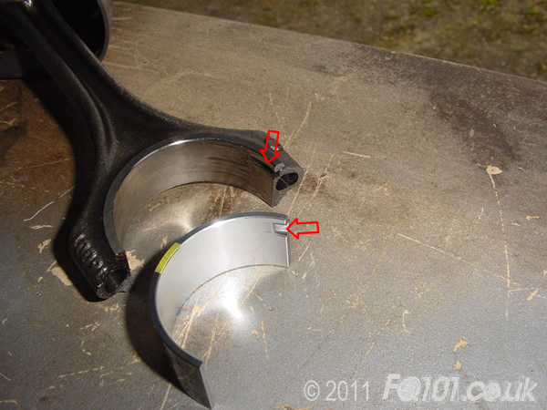
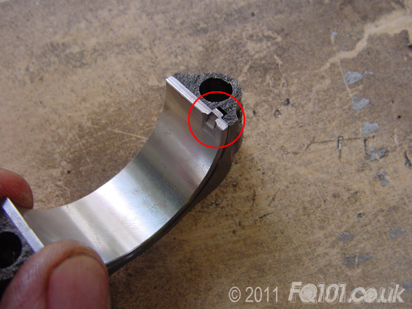
Locate the bearing in the conrod cap as shown. Line up the notches as shown and press the bearing in place.
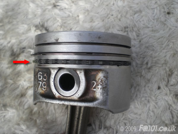
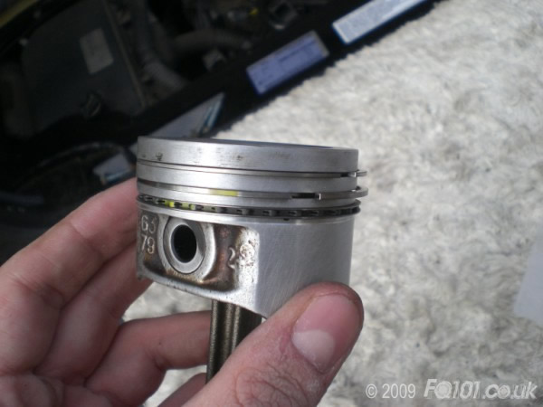
When you fit the piston, ensure that the yellow mark on the bearing faces towards the timing chain.
Using your piston ring compressor (you will need one, you have zero chance without it!), compress the rings.
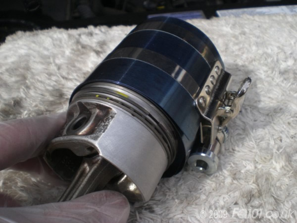
Locate into the cylinder.
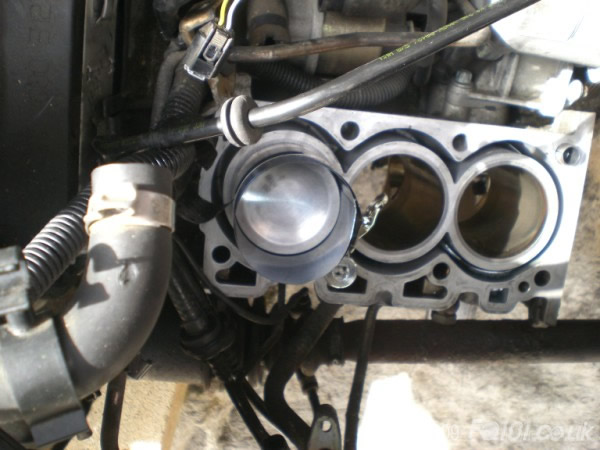
Using a soft driver (rubber handle of a hammer, bit of wood etc), hit the top of the piston firmly and squarely, 1 hit is all that is needed.
If it feels like it is catching, then one of the rings may have popped out of the compressor, so remove and refit.
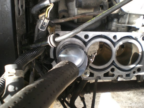
If you fitted the pistons with the yellow mark pointing towards the timing chain, the etched arrows on top of the pistons will be pointing towards the right. Make sure that they are.
Refit the conrod caps ensuring they are the correct way around.
We also used brand new con-rod bolts, torqued to 15Nm & 90 degrees.
With the mounting face of the lower block clean, liberally apply sealant (any HT sump sealant will work).
Be sure to apply around all bolt holes for maximum seal.
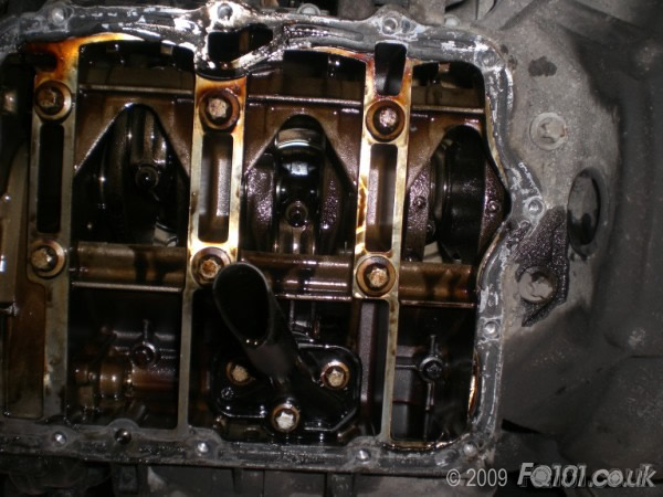
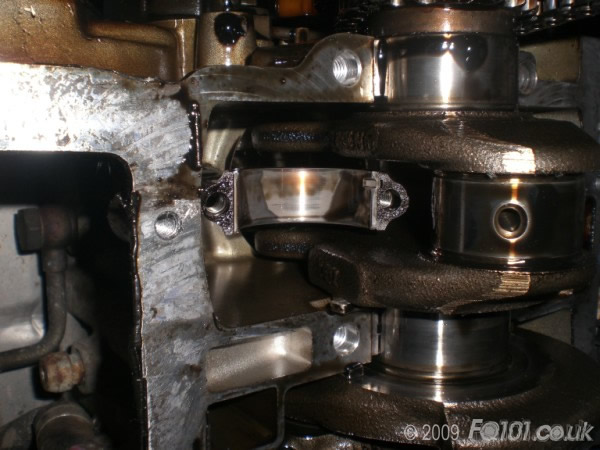
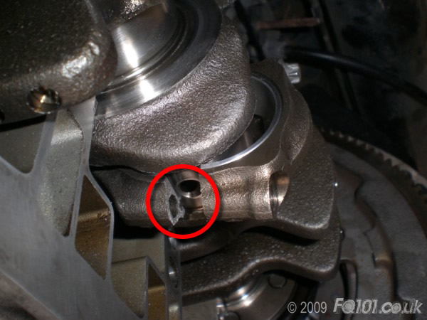
Before fitting the lower section of the block, you need to locate the crank bearings between cylinders 1 and 2. This is a tricky job to do as they don't seem to sit how you might expect! Providing they look as shown in the following picture, then you are ok.
Fit and tighten the main crankshaft bolts to 35Nm then 62 degrees.
Tighten the rest of the remaining bolts.
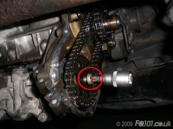
Refit the oil pump sprocket.
Use a spare extension bar to stop the sprocket from rotating as you tighten the securing bolt.
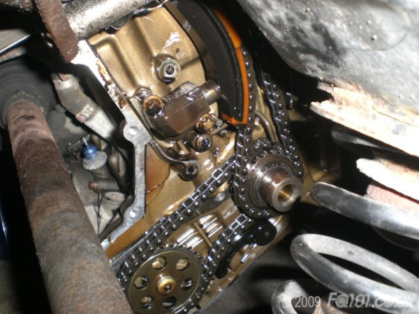
Fit the new timing chain slider onto the pin, but obviously it cannot be secured at the top of the engine until the head goes back on.
Make sure the crankshaft sprocket sprayer is all attached, the chain looped round and tied up the top, and the hydraulic timing chain tensioner is all tight (if you removed/loosened it).
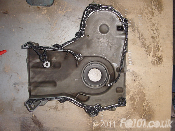
Apply gasket to the timing case as follows:
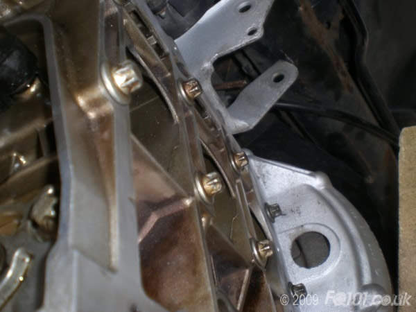
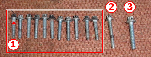
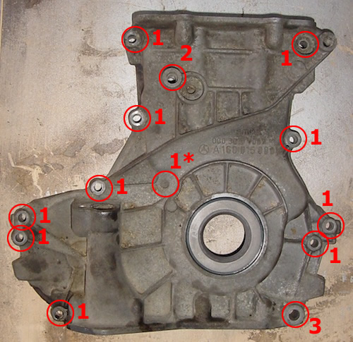
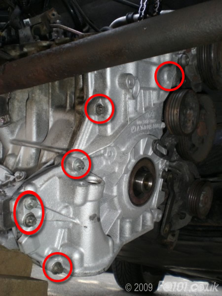
Get your timing cover bolts ready. There are 3 different types which go in the cover and these are labeled in the following two pictures to show you where they all go. Note: if you have a pre-2001 model, you will have an extra bolt. This one (and it's location) is identified with an asteris:
Refit the timing cover and bolt it all back up, but remember that you cannot bolt from the top yet as the head must go back on.
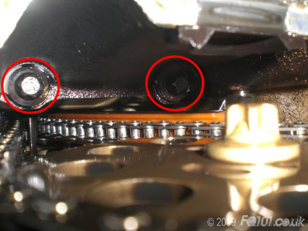
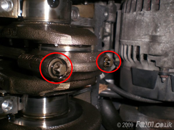
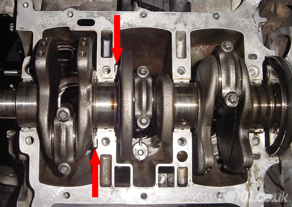
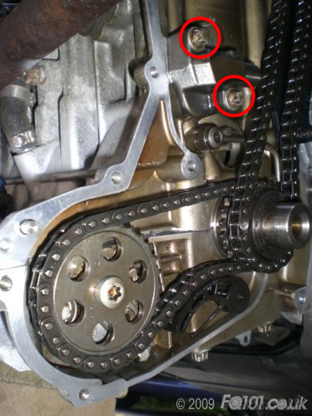
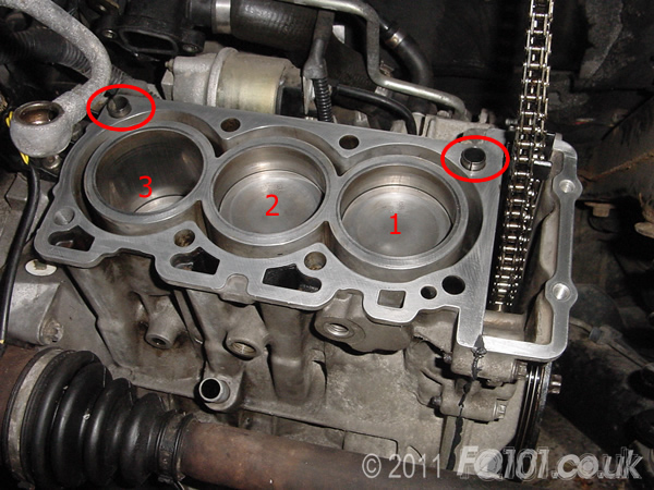
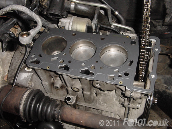
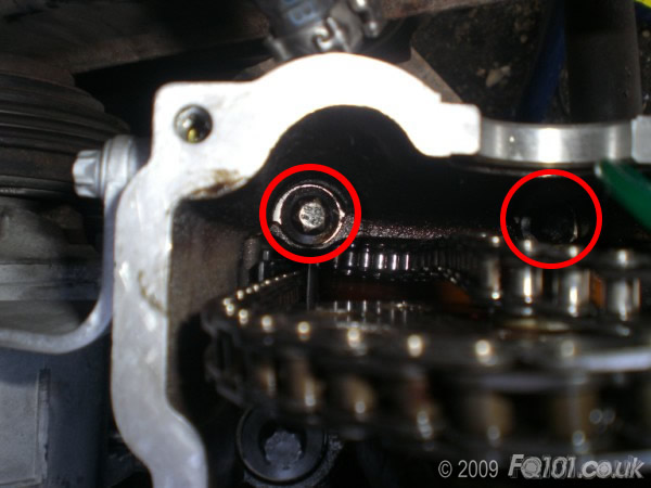
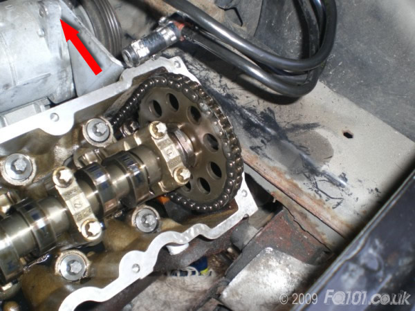
Before refitting the cylinder head, turn the crankshaft by hand in a a clockwise direction. As cylinder 1 comes up to TDC, line it up with cylinder 2 as shown in the following picture. Ensure that the two dowels are fitted in the engine block as circled.
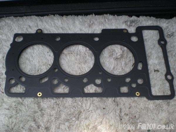
Take your cylinder head gasket and locate on the dowels in the block face.
Refit the cylinder head. Note the new slide rail you fitted must clip into the bar on the cylinder head.
Using your NEW bolts, tighten to 21Nm, followed by 3x90 degrees (2x90 degrees if you have a 700), finally 1x10 degree turn.
Tighten in the order shown.
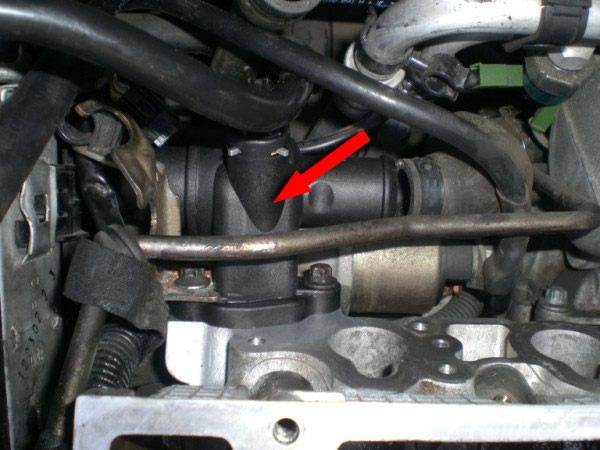
We also took the precautionary measure of changing the thermostat. This is a difficult job to do normally, and the space created by this work is very welcome.
Tighten the final 2 timing cover bolts.
Reattach the engine mount and the air-con compressor back onto the cylinder head.
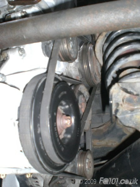
Refit the alternator mount, the pulley spacer, the pulley and all belts, then re-tension.
Remember you still have the sump off the engine to chock the crankshaft whilst you tighten it.
Now time the engine using this guide.
Refit the 3 bolts in the crankcase.
Refit the oil pick-up pipe.
With the face of the sump cleaned up, use liberal amounts of sealant, again all around the bolt holes and offer up to the bottom of the crankcase. Hold in place with 1 bolt at each corner.
Tighten with the remaining bolts.(12Nm)
Fit the turbo manifold gasket (locate it on the new studs).
Push the turbo back onto the studs and gasket.
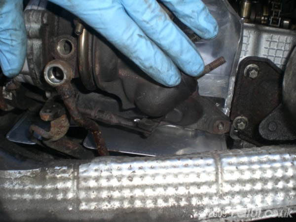
Tighten the turbo studs (6Nm), and refit all the water/oil feed pipes.
Refit the cam-cover (12Nm)
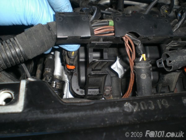
Refit the coil packs.
Remember to reconnect the earth wire to the first pack.
Plug in the coil packs.
Before refitting the inlet manifold, it's worth relocating the rear engine mount again. Jack the engine back up and secure the mount back with its 17mm bolt and nut. This will give better angles to refit the inlet manifold.
Refit the injectors and the inlet manifold (reconnecting the intercooler pipes and sensors).
Refit the TIK including brackets, plus all turbo pipework.
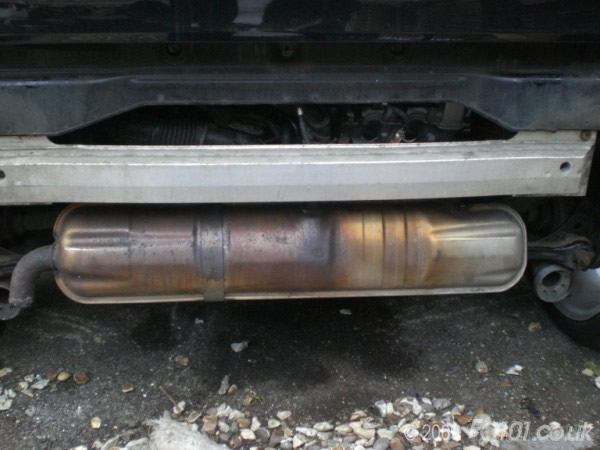
Refit the exhaust and the rear crashbar.
Fill up with oil and Test!
We also changed the fuel filter, which meant that the fuel lines were empty - this is a good thing as it allows the engine to circulate the oil into the bearings and the tappets before firing up and loading the engine.
Remember to bleed the coolant system before using.
It is advisable to follow the standard 'running in' procedure to ensure that the new components settle in okay.


