

Before you begin, make sure that you disconnect the battery.
Then remove the rear panel and crash bar.
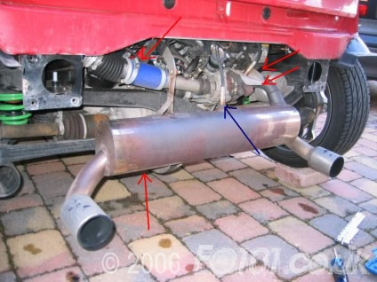
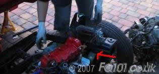
Undo the lambda sensor from the exhaust. If you have a mk1 to mk3 you won't have a second sensor. Remove the exhaust; depending on your exhaust manufacturer there may be different mounting points. Also remember to undo the lambda sensor arrowed in blue. The exhaust mounts on the gear box need to be undone using an E12 bit, the turbo nuts require a 13mm spanner; the lambda sensor needs a 22mm spanner.
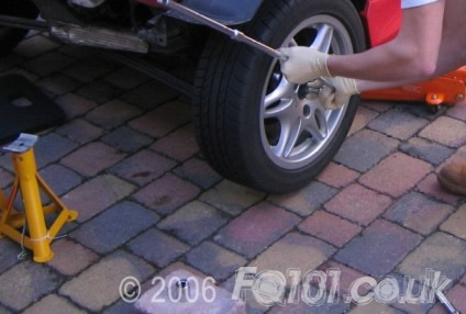
Slacken the drive shaft bolts, but leave them in situ. You need to use the weight of the car on the ground with the handbrake on to get enough force to slacken them off.
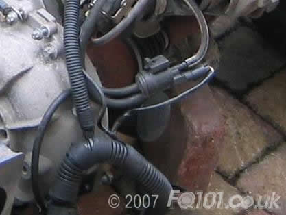
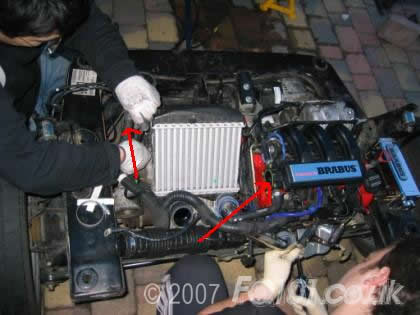
Remove the jubilee clips holding the TIK in place and disconnect the three pipes connected. They should pull off fairly easily although a screwdriver may help removing the clipped pipe.
Be very careful when removing the small pipe on the rear as it's small and quite brittle.
All that is now holding the TIK to the car is the supporting bracket. Undo the two small E bolts holding it to the top of the gearbox (also has an earth cable on one of the bolts).
Now disconnect the airbox end of the TIK and pull it out slightly so it gives enough slack to remove it from the turbo inlet; it should now move fairly freely. Twist the unit around to access the bolts securing the TIK to the bracket being very careful not to break or crimp any pipes attached to the electronic device.
Remove the bolts so the TIK is now totally removed from the car.
To remove the intercooler pipes, undo the jubilee clips from the top pipe - there is one jubilee each end, one on the intercooler and the other at the throttle body.
Remove the other two clips holding the lower pipe on - one at the turbo, the other at the intercooler connection.
Pull both pipes clear of the car.
The engine wiring harness needs to be disconnected: unclip the ECU (remember to push the slide clips out before pulling on the wire!!)
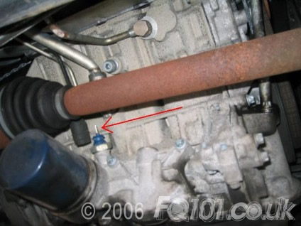
Undo the oil pressure sender (shown below - it's a spade connector and rubber cap).
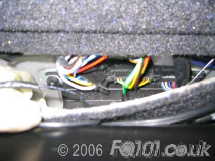
There is one branch from the ECU into the cabin. You need to pull up the carpet behind the passenger seat, and undo the connector with the red, blue and wires.
This then needs to be fed back through the rear bulkhead grommet.
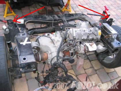
Now jack up the car, and mount some axle stands under the engine sub-frame, AND under the Tridion jacking points.

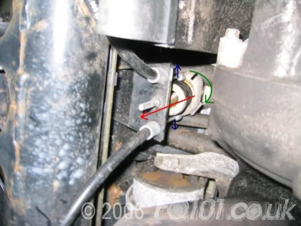
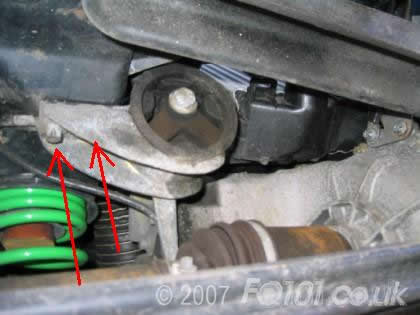
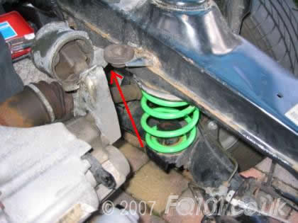
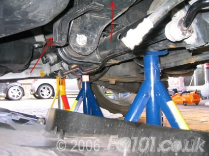
Pull the cable bracket down on the return spring (red arrows), pull the cables out of the guides at either side (blue arrows), then twist the bracket (green arrows) …. All with one hand!!
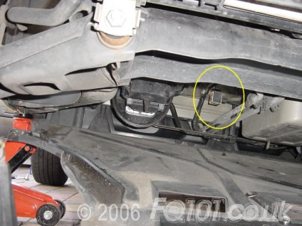
Whilst under there, it may be advantageous to drop the front floor pan (6 x 8mm bolts), and unplug the lateral g-force sensor. The wire attached to this needs to be fed right back through to the engine.
G-force sensor pictured below.
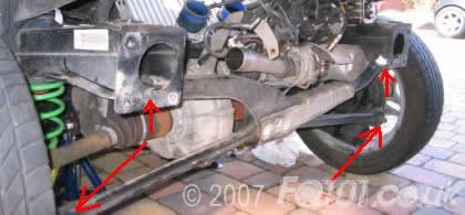
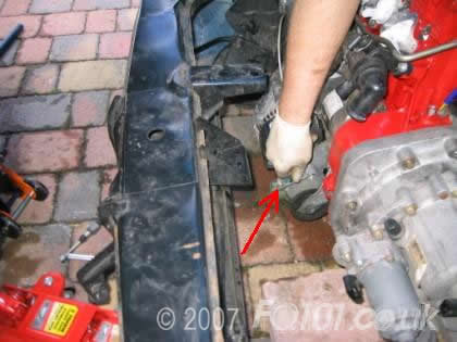
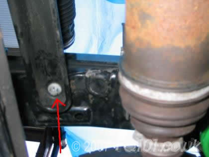
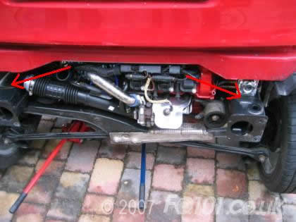
You can start to lower the engine by undoing the main chassis securing bolts (E18).

There are four of them in the locations shown. Only lower the engine by about 1-1.5 inches at this stage.
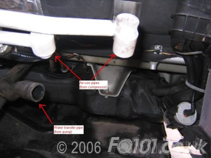
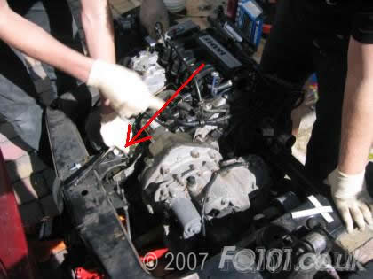
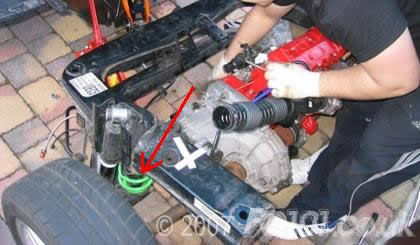
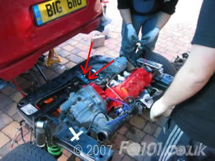
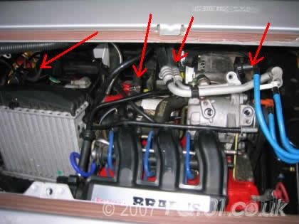
Remove all of the attached hoses; these include the water transfer pipes, rear brake hoses, fuel lines, ABS sensor wires and air-con pipes.
The rear brake pipe requires a 15mm and a 13mm spanner.
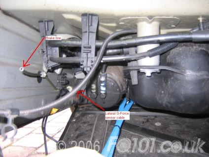
The water transfer pipes are secured via Jubilee clips; the fuel lines are slide clips (blue in the picture, as standard they are black), and the air-con pipes are attached via a T40 torx bit. Please remember to de-gas the system correctly.
Also pull through the lateral g-force sensor cable.
Continue to (slowly) undo the chassis bolts, until the engine is fully lowered, and remove the bolts.
Replace the Rear axle stands, with 1 jack securely located on the sub-frame/chassis mount.
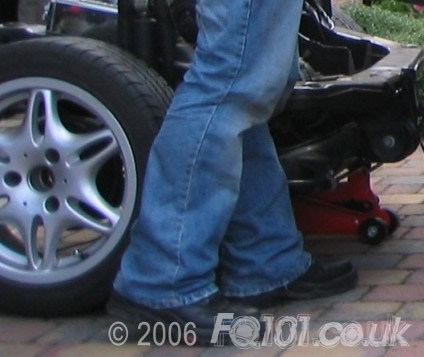
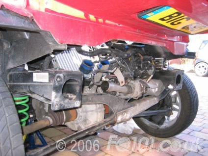
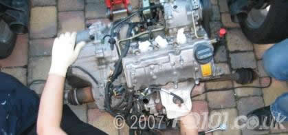
Carefully wheel the engine out, it's a very close fit and you have to manipulate the rear arches as the suspension assembly moves. Ensure there are no further hoses/cables/wires attached to the car, and the whole sub-frame/chassis arrangement should now be free.
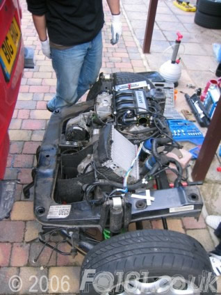
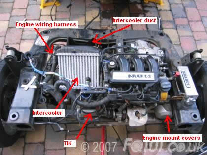
Once the engine is removed from the car, you need to identify the components that you either wish to keep, or which would obstruct the removal of the engine from the subframe. These would be things like:
- Intercooler
- Intercooler duct
- Intercooler fan (and wiring)
- Engine Wiring Loom
- Engine mount covers
- TIK
You may wish to remove other components for additional access. Remember to disconnect the HT leads from the top bank of plugs.
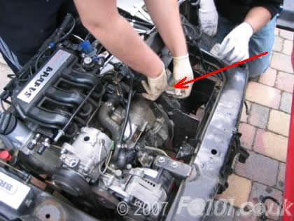
To allow more access, remove the 2 x E10 bits holding the fuel rail to the inlet manifold.
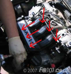
Rock the inlet manifold forward to gain access to the rear bolts on the manifold - there are 6 x E10 holding the manifold on. A universal joint socket may be advantageous here.
Unplug the IAT and MAP sensor, disconnect the two fuel lines and the vacuum line. Disconnect he oil breather hose from the top of the throttle body, then unplug the throttle body connection, and also remove the top intercooler pipe.
Remove the vacuum hose from the FPR, and disconnect the vacuum hose from the wastegate to the inlet manifold.
Flip the inlet manifold back over (towards the front of the car) and disconnect the injector connections. Disconnect the coils, the EGR valve and cycle valve.
Once the wiring harness is removed, the 3 coil packs need to be also removed (if you are retaining them); they are held on by 2x E10 each.
Ensure the base of the engine is thoroughly supported! We used bricks to take the weight of the engine.
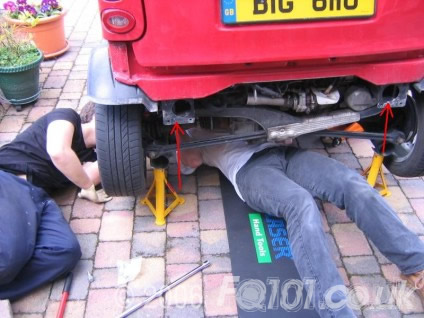
Remove the tie rods which hold the subrame in tension, then undo the main rear crossmember from the chassis rail.
With the engine supported, remove the rear engine mount.
We found it much easier to remove the mounts from the chassis frame rather than remove the mounts from the engine.
This means that you can simply transfer the mounts to the new engine prior to refit.
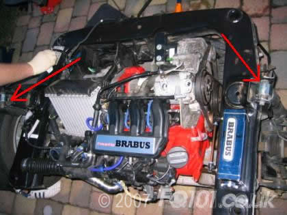
Now carefully remove the side engine mounts (E15).
Due to the fact the engine has been removed in the frame and supported on the wheels, you will not be able to get enough height in the engine to free the driveshafts without the gearbox hitting the chassis.
To allow room to move the engine, you can remove the suspension from the top mounts i.e. where it joins to the chassis.
The top chassis is only resting in place now, so you can lift this off completely, or get someone to hold it up whilst the engine and gearbox are removed.
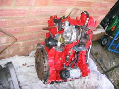
It is best to prepare your engine prior to swap over. We stripped the engine back to the bare engine block with no ancilliaries attached, then painted it in heat resistant paint.
We bolted on the new turbo, re-attached the alternator, air conditioning pump, and the various transfer pipes.
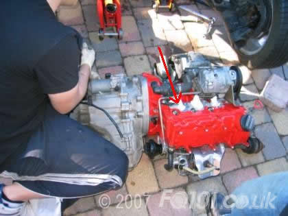
We retained the existing gearbox, which was easy to swap with the engine on the floor. It required removing the existing eight bolts and refitting to the new engine.
A quick tip whilst transferring the new engine is to block up the inlet ports with some clean rags or tissues to stop dirt/bolts/small children dropping into the engine during the change.
To make it easier in refitting, we again removed the chassis from the subframe. This gives enough access to lift the engine into its approximate position.
After carefully lifting the engine into place, making sure the driveshafts go into the splined hubs, the chassis can be carefully placed back 'over' the engine.
Remember to put the suspension springs back in place before you place the chassis rail.
Carefully pivot the engine round until the rear engine mount is approaching the chassis rail.
Bolt up the side engine mounts before tightening the rear mount, as these should hold the engine assembly in a more central position.
With the two side engine mounts connected, the engine can be carefully secured at the back mount.
With the engine now held in place, you can reattach the rear cross member and tierods.
Reattach the engine harness, inlet manifold, ignition coils etc.

Reattach the upper suspension mounts.
Ensure that all other bolts are tight, and the engine is ready for re-mounting back into the car.
With the engine in the subframe ready for mounting, it is wise to ensure that all of the bolts are tight, as access becomes a lot more restricted when the engine is raised back into place.
With the weight taken on a jack at the back of the engine (as was removed), gently roll the engine under the back of the car. You may need to lower the engine slightly to ensure it can clear the back of the trid.
Roll the engine in until it is about 6-12 inches from the back of the bulkhead. Ensure that no pipes/cables are caught as you roll in.
You need to be mindful of the aircon pipes, water pipes, engine wiring loom, ABS sensor wires, Brake lines, the fuel lines and the handbrake pin which will be protruding lower than the subframe at this stage.
Reconnect all pipes etc, then roll the engine back into position. Whilst doing this you will need to carefully bend the handbrake pin over the edge of the subframe until it locates in its guide. Reconnect the handbrake cable by pulling the pin down and sliding the cables into slots on the securing ring. (opposite of removal).

You can locate and start to take the weight of the engine by reattaching the main chassis bolts (E18).
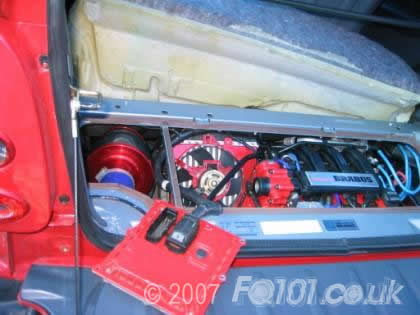
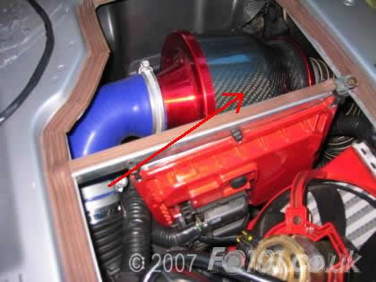
Here we re-fitted our induction kit and ECU, but if this your car utilises the original airbox, this locates in the standard mounts on the chassis rail.
Remember to ensure that the battery is DISCONNECTED when reconnecting the ECU.
With the engine bay almost complete, reattach the exhaust and lambda sensors.

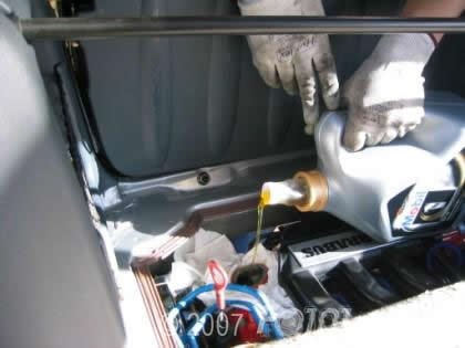
Top up the engine with fresh fluids.
Now it is time to test! Upon first turn we encountered no problems and engine fired and ran perfectly. Click here for a video of this car running.
The most common failure following a job like this will be something as simple as a sensor circuit failure, so if you have access to a comprehensive fault-code reader, it will be a big advantage.
Remember you will need to bleed the brakes, and the coolant system before normal use.


