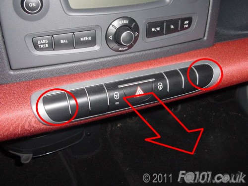
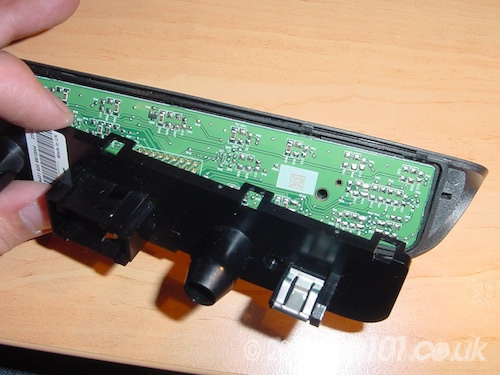
To access the button strip LEDs, pull the strip out of the dash in the direction shown. It is held in place with two clips roughly where the circles are.
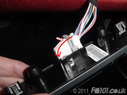
Release the wiring by pushing the the white clip and swing down the grey arm. The connector will come away freely.
Look at the back of the button strip. The assembly simply clips together in the locations circled below.
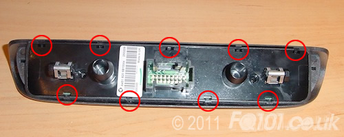
Release the clips as shown and the back section will separate. You can do this by hand.

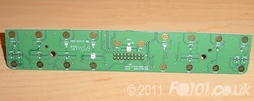
Remove the back section to reveal the PCB.
The button strip will separate into its constituent components.
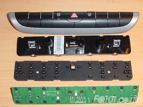
You can see the LEDs on the front of the PCB. You may have more LEDs depending on the additional button functions you have. This particular strip came from a car with just the central locking and hazard light buttons working.
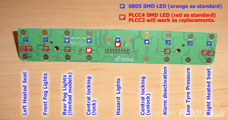
There are two types of LEDs on the board, one smaller than the other.
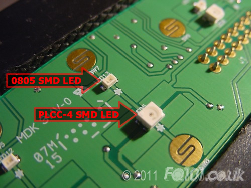
For the PLCC-4 LEDs, you can substitute PLCC-2 LEDs as LED channels 3 & 4 are not used.
The 0805 LEDs are very small and difficult to handle. The PLCC LED's orientation is characterised by the triangular cut-out on the top. The 0805 LED orientation marker is usually on the bottom. For the following LEDs, the centre bar of the 'T' points to the cathode.
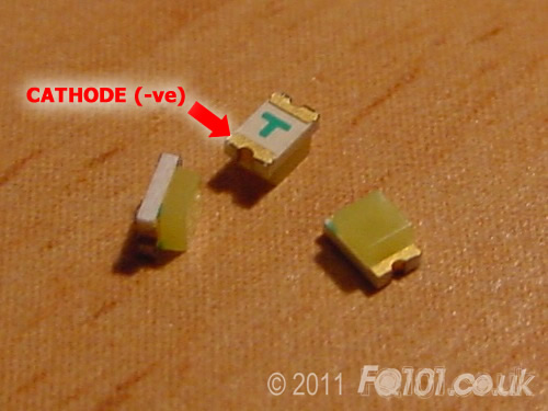
For diagramatic purposes, we have used the triangular cut representationout for both LEDs. The full list of LEDs and their functions are shown below (click to make larger).
In the example below, we changed the backlights to white: