Turbo problems are often queried on forums, social media and through our own help ticket system. However, when describing issues, it is useful to correctly name to components so that both parties understand what is being discussed.
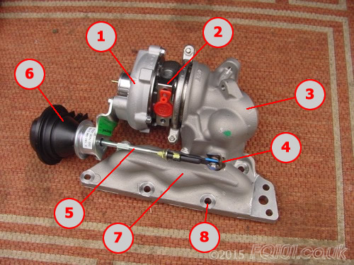
The following image shows a complete turbo assembly as purchased from smart. This particular model is a 60kW unit which is found as standard on the Roadsters (not Brabus) and the Brabus fortwo 450s. The numbered components are as follows:
- Turbo compressor housing to which the TIK and the first intercooler pipe connect.
- Turbo bearing body with connections for oil lines and coolant lines
- Turbo exhaust gas body for connection of the exhaust and the first lambda sensor
- Wastegate
- Wastegate actuator arm
- Wastegate actuator
- Manifold which can be prone to cracking - more of a problem on the 599cc turbos.
- Mounting holes (8 for this turbo, 7 for the 599cc turbos).
It is worth noting that turbos for all 698cc engines have a machined section on the manifold where the pre-heater pump pipe connects. This can be seen on the right hand side of the manifold (7) where there the pipe and two mounting studs are fixed.
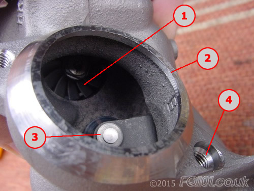
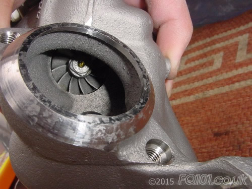
This is a close up detail of the exhaust connection side of the turbo assembly. Looking inside you can see the following:
- Exhaust gas impeller through which all engine exhaust gases pass through when the turbo is boosting.
- Exhaust opening with a machined finished to allow the exhaust downpipe to fit snugly.
- Wastegate- this allows the gases to bypass the impeller when boost is no longer required. The most significant of these occurrences happens during gear changes and it is possible to hear a slight "chatter".
Either side of the opening, there are two threaded holes (4) which are where the exhaust mounting studs are fixed.
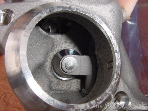
A closer look at the wastegate in the closed position:
A closer look at the exhaust gas impeller:
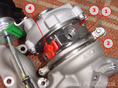
The turbo bearing body fits between the exhaust and inlet sides of the turbo. Through the middle of the body is a shaft which is turned by the exhaust gas impeller which directly turns the inlet air compressor wheel. The components are as follows:
- Turbo bearing body
- Clasp which holds the turbo bearing body (1) to the exhaust manifold.
- Coolant pipe connection (there are two connections in total - one is on the other side of the body)
- Oil pipe connection (the red bungs are inserted at manufacture as there is a small amount of oil already within - these are removed upon fitting)
With its close proximity to the cylinder head and channelling of exhaust gases through the exhaust manifold, the turbo assembly gets very hot. The coolant helps to lower the temperature of the bearing body to prevent warping. The oil lines are used for lubricating the impeller shaft and bearings.
Looking at the compressor side of the turbo assembly, there are the following components:
- Inlet air connection (TIK connection)
- Compressor wheel which is driven by the impeller shaft
- Boost air nipple which takes a sample of boost air for control purposes
Air is drawn into the turbo by the compressor wheel and forces this around the chamber beneath the wheel. The compressed air is spun in a clockwise direction under the lettering before being forced our of the opening on the right hand side of the image.
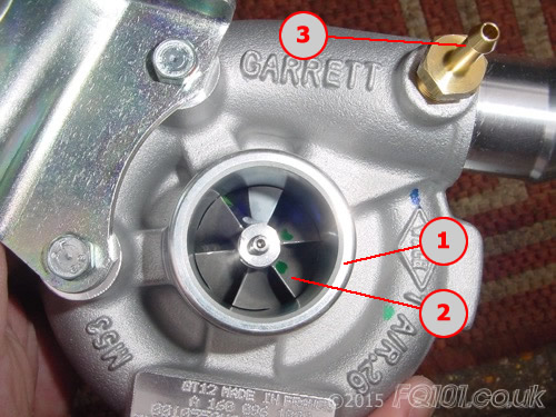
The boost air from the nipple is taken to the boost control solenoid (or cycle valve) and is used for operation of the turbo wastegate. Boost air is forced into the turbo actuator which pulls the actuator arm and opens the wastegate. A detail showing this arrangement can be found here.
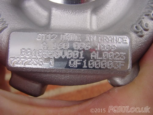
The compressor side of the turbo also has the name plate with the part number and manufacturing details stamped on: